Bounding boxes are used constantly in engineering for a variety of reasons. Amongst SolidWorks users, I frequently see them used to optimize plant floor layouts, packaging sizes, and stock lengths. In this blog post, I want to cover the pros and cons of the various techniques available in the SolidWorks API for determining them.
GetBox / GetBodyBox / GetPartBox
The SolidWorks API comes with several API calls that return the coordinates of two of the bounding box corners. From these 6 double values, all of the bounding box coordinates can be obtained. These methods are:
- IBody2::GetBodyBox
- IComponent2::GetBox
- IFace2::GetBox
- IAssemblyDoc::GetBox
- IPartDoc::GetPartBox
The obvious advantage to these methods are their ease of use. They have two notable downsides, however. First, these methods do not always return the true minimum boundary box, sometimes even being 5-10% off in some directions (in my personal experience). Second, they only return the bounding box in the primary coordinate system. If the body you wish to analyze is rotated, this could render these methods useless to you.
Our Macro Library contains an example of IBody2::GetBodyBox, available to any CADSharp.com member.
IFace2::GetTessTriangles
According to the API Help, this method “gets the triangles that make up the shaded picture tessellation for [a] face”. Practically, this means that if we want a more accurate bounding box than the methods described earlier, we can traverse every face in a body and discover the largest and smallest X, Y, and Z values in that body. For each face, we can also transform the tessellation triangle coordinates into another coordinate system, if desired. That way we are not limited to finding the bounding box in just the primary coordinate system.
Even this approach, however, might be unsuitable for machining applications. The API Help remarks for this method state, “These triangles are intended for graphics display purposes and do not represent a tessellation that can be used, for example, by a machining application. If you need the kind of accuracy associated with a machining product, traverse the body faces and extract the topology and geometry data to create your own faceting.”
Our Macro Library contains an example of using IFace2::GetTessTriangles to obtain the bounding box of a body, available to any CADSharp.com member.
IModelDocExtension::Create3DBoundingBox
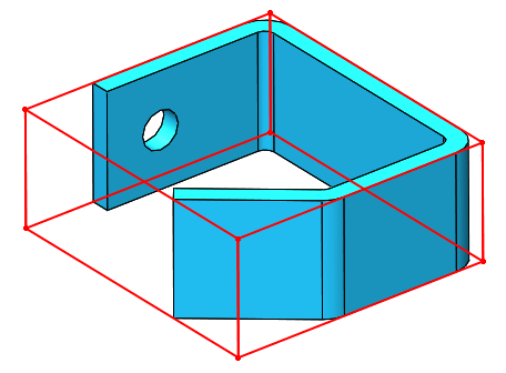
This method, available as of SolidWorks 2013, creates a 3D sketch containing lines representing what SolidWorks considers to be the “ideal” bounding box for a cut list item. The sketch can be accessed via the API and the actual bounding box points retrieved (in the standard coordinate system). The bounding box created by this method is the same one used to calculate the built-in LENGTH custom property for a Structural Member feature in a weldment part.
Personally, I would hesitate to use this method for bodies not created from Structural Members, for two reasons. The first and less significant reason is that it requires generating a cut list for your model, which might be undesirable. Second, and more significantly: the “ideal” bounding box it returns might not actually be the one you need. For example, consider the following body created by a regular Extrude feature and then rotated at an odd angle with the Move/Copy Body feature:
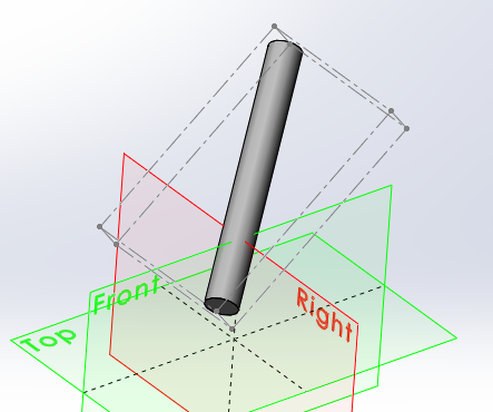
This bounding box correctly identifies the diameter of the body and therefore returns a more accurate width than IBody2::GetBodyBox would, nevertheless the direction of the body is not recognized and therefore the height and length are still incorrect.
If you want to experiment with method on your own to see if it will meet your requirements, check out the example in our Macro Library, available to any CADSharp.com member.
IBody2::GetExtremePoint
Technically, this method does not return bounding box coordinates, but it can be used to return the length of a bounding box in a specified direction. This is really useful for obtaining the length of a body that was not created with a Structural Member feature but might also be a strange angle. (Again, keep in mind that if it was created with a Structural Member feature then we could simply use the built-in length custom property, and if the desired length were aligned with one of the primary axes then we could obtain the length with one of the other bounding box techniques.)
Unfortunately, getting to that length value using this API call is not easy. First, this method requires a direction. Obtaining that direction programmatically could be a challenge. Second, once the extreme points in that direction and its reverse and obtained, you still will not have the extreme length because the line connecting the extreme points is not necessarily parallel to the direction you want. For example, consider the following body.
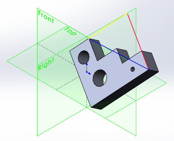
Using the normal of the large bottom face as the positive direction (represented by the red line) and its reverse for the negative direction will result in the two points connected by the blue line. Since this blue line is not parallel to the red line, the blue line does not represent the “extreme length” of the model for the chosen direction. Rather, the red line actually represents the desired “extreme length”.
We can get the length of the red line using some vector algebra. Since we know the red and blue lines form the hypotenuse and adjacent of a right triangle (the yellow line is the opposite), we know that if we get the angle between the red and blue line, we can calculate the length of the red line by multiplying the length of the blue by the cosine of that angle. That angle is equal to the arccosine of the dot product of the unit vectors of the red and blue lines.
Available to CADSharp.com Power User members only is a very powerful macro in our Macro Library that uses IBody2::GetExtremePoint to calculate the “extreme length” of a input. To specify the direction, you can pass in a plane, planar face, cylindrical face, straight edge, or circular edge.
In conclusion, the SolidWorks API has many options for obtaining bounding boxes, depending on your needs. If you have another technique you have used in the past, please share it in the comments below.
Keith
Want to learn about new macros, videos, and upcoming training events? Sign up for our newsletter.
Leave A Comment
You must be logged in to post a comment.