Join Us At SolidWorks World 2018
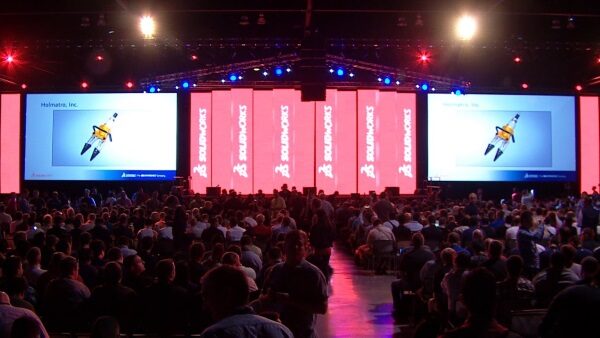
We are excited to announce that we will presenting and exhibiting at SolidWorks World 2018 in Los Angeles, CA on Feb 4-7. If you’ve never been, I highly encourage you to attend this high-energy event that I like to describe as “one-third learning, one-third networking, and one-third party”. If you are a CADSharp customer or simply have an interest in the SolidWorks API, here’s some ways you can join us:
Beginner and Advanced API Presentations
Getting Serious with the SolidWorks API – Tuesday, Feb 6, 10:30 AM – 12:00 PM – Have you hit a ceiling in your API skills? Is your code a patchwork of recorded macros and other peoples’ code? Can you barely make sense of most API code? Using live examples, this session will take you take control of your code by demystifying the SOLIDWORKS API Object Model and the API Help.
Write a SolidWorks Addin From Scratch – Monday, Feb 5, 10:30 AM – 12:00 PM – Curious how professional developers create add-ins from the ground up? This hands-on session, which assumes attendees have at least a basic knowledge of object-oriented programming, will walk through DLL registration, hooking into SOLIDWORKS, menu creation, and debugging in Visual Studio.
Visit Our Exhibit Booth for Macro Mania!
Please visit us at Partner Pavilion booth 533, which is located in directly in the back of the hall near Model Mania. Our exhibit will feature customer case studies, upcoming product demos, and our own “Macro Mania”! The latter gives you opportunity to test your skills at writing a macro from scratch using only the SolidWorks API Help for reference. Top three finishers will receive an Amazon gift card.
Even if competition isn’t for you, please stop by to have a chat and learn about our upcoming products and events. For example, we will be unveiling “PMP Sandbox”, which is a tool that allows you to quickly generate PropertyManagerPages code (VBA, VB.NET, or C#) using a GUI.
Meet With Our Technical Director
If you have any interest in meeting with our Technical Director, Keith Rice, to talk about your automation needs, please email him and he’ll make sure he’s at the CADSharp booth at that time. Thanks and see you in LA!
Want to keep up with future content, training, and events like SolidWorks World? Join our monthly newsletter!
Technical Support Now Available Via Slack
![]()
One of the most valuable benefits of a CADSharp.com Power User membership is the on-demand technical support (SolidWorks API and SolidWorks PDM API) we provide to our customers. Previously this technical support was available only via email. As of today, we are now giving customers the option to ask questions and start discussions in CADSharp’s Slack. Below I’ll explain what this is and why you might consider using it.
What is Slack?
Slack is a communication tool that tries to take the best elements of email, Facebook, and forums and roll them into one. Companies use it so that its employees, contractors, and customers can communicate more efficiently. Communication occurs mostly in public or private “channels”. Private channels can only be seen and used by people specifically invited to those channels, whereas public channels can be seen and used by anyone in that Slack community.
A Slack account is free and can be used via web browser, desktop client, or mobile app. Personally, I prefer the desktop client, which I can hide in the Windows system tray while it is running.
Why use our Slack instead of email?
While Slack might seem like just another tool to keep track of and remember a password for, it has several benefits that make it superior to getting tech support versus email:
1. Every CADSharp.com team member can instantly see your issue. As a result, you’re going to get help MUCH more quickly than if the issue must be funneled through me first.
2. You can see and search the history of all CADSharp tech support inquiries. This means that the entire CADSharp.com community is benefiting from everyone else.
3. Uploading images, files, and code snippets is MUCH easier through Slack than through email. Trust me, you’ll fall in love with the user interface. No more worries about file attachment size or email destroying your code’s formatting.
4. Slack keeps discussions organized in threads, just like in a forum. No more archiving messy email chains or accidentally deleting or losing the info you need.
What happens when my Power User membership expires?
Nothing, actually. We don’t kick you from our Slack, we just ask that you refrain from creating new questions and discussions until you renew your membership. You can still respond to other people’s questions, of course.
Show me the money!
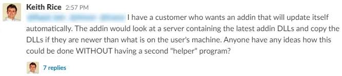
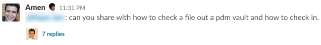
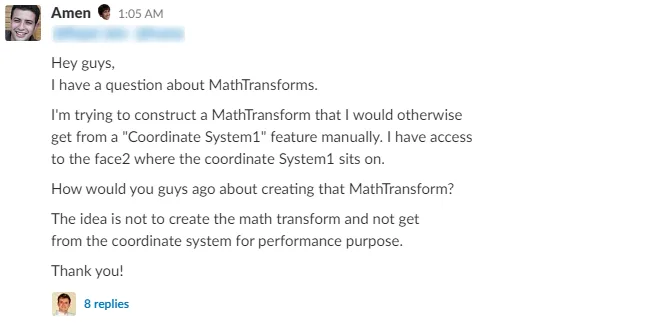
Here are three examples of questions that were asked and answered within a single business day, with replies provided by several CADSharp team members:
You’ve no doubt heard the saying, “Too good to be true.” We’re proving that adage wrong right now and we’re incredibly excited about it. Join hundreds of other satisfied Power User members today and start getting on-demend tech support from the best SolidWorks API minds in the world!
Keith
Want to keep up with new training events, blog posts, code snippets and more? Sign up for our newsletter.
Productivity Software and Tools That I Use
In this post I want to give you a peek inside how I organize myself as a software developer, software development team leader, and small business owner. Consequently, you’ll learn something not only about how I develop software but also how I run CADSharp. But before we get started, I want to make a few comments about productivity tools in general:
1. You will never find the perfect solution, so find something that works for you and just stick with it. The list of productivity and organizational tools is never-ending and many of them are largely redundant or only offer minute benefits over their competitors. Generally, you want to stick with tried and true options that obviously do not have an obvious overlap with your other tools.
2. Use a tool because it obviously makes you more productive / organized and for no other reason. If it is not clear to you how a tool might make you more productive or if the thought of using it stresses you out, don’t use it. It has taken me over five years to arrive at the point I am now. In some cases, I had to do something the inefficient way for years before it clicked in my mind how I ought to be doing it.
3. Don’t avoid a tool just because you’re afraid of the upfront work involved. This is the flip-side to the above: while you don’t want to force yourself into a workflow you’re not ready for, you could be hurting yourself by sticking with a workflow you know is inefficient. In my case, I balked at first of the hours it would take to migrate all of my prospective customers from Excel into Insightly (which I discuss below), but once I pulled the trigger it was a huge relief.
Now, onto the software and tools I use.
Visual Studio
Visual Studio Community Edition 2017 is the IDE (Integrated Development Environment) that I use to write code in. Yes, you can write .NET programs in any text editor, but no sane person would ever do this unless they’re either masochistic or trying to prove something to yourself to the world. Anyway, why do I use the Community Edition specifically instead of a paid editions (Professional and Enterprise)?
1. It is free for individual developers, open source development, classroom learning, or development teams of up to five developers working at organizations with less than $1 million in annual revenue. (Learn more about the limitations at the bottom of this link.)
2. It does everything I need and much more. Whereas the old Visual Studio Express Editions had limitations that were annoying to addin developers (since they required tedious workarounds), VSCE has very few limitations that are relevant to SolidWorks API developers. You can compare all of the editions here.
3. I prefer to use the same tools that my training students use. Since anyone can use VSCE for classroom learning, I prefer that all of my students are working with the exact same program I’m using to avoid any extra obstacles.
BitBucket
Think of BitBucket as the programming equivalent of SolidWorks PDM, except in the programming world, it’s not called “PDM” but “SCM” (Source Code Management). SCM lets you manage revisions and control code access. Where it gets confusing is that BitBucket isn’t source control itself (the SCM system I use is actually called Git) but rather a service that let’s you store your repositories online so that you can collaborate with your team or customers more easily. If you’re new to source control, it’s a bit confusing at first but soon becomes apparent how essential it is.
BitBucket has a famous competitor called GitHub. I use BitBucket because they allow free private repositories, whereas GitHub is only free for open-source (i.e., public) repositories. Beyond that, I can’t think of a reason I’m using BitBucket over GitHub. They both have great user interfaces, issue trackers, third-party tool integration, and everything else you could possibly want.
Alternatives: Microsoft’s SCM is called Team Foundation Server and their BitBucket / GitHub equivalent is called Visual Studio Team Services. These tools are integrated into Visual Studio. I have never used these tools so I can’t comment on their quality or ease of use for small development teams.
SourceTree
SourceTree is made by the same company that makes BitBucket (Atlassian) and is usually used in combination with BitBucket. I mentioned that BitBucket is an online tool for storing your code and collaborating with your team. Well, what about when you work on your code locally? How do you commit code (i.e., create revisions) in your local repository before its ready to push to your online repository? Well, Git (the name of source control system I use) lets you do all of that from the command line. Working from a command line, however, can be tedious. Enter SourceTree, which gives you a visual interface for common Git commands also a visual layout of your repository and its commit history. Is SourceTree necessary? No. Is it really useful? I think so.
Evernote
Evernote is a tool for remembering / storing information. Think of it as a database for text, images, and sound that you can easily organize and search. I use it to store lots of information about my business: code samples, programming tips, SolidWorks API technical support emails (that I copied and pasted into Evernote), the .NET guides I sell, blog post ideas, interview notes with prospective contractors, ideas for future projects, etc. Basically, anything that I would have kept in Word, Notepad, PDF, or email years ago. The problem is that searching for what you need is very difficult. You can’t search the contents of documents on your hard-drive en masse and working out of email is just annoying. Evernote solves this nicely: ALL of my infomation is in ONE place (though the information is still divided into separate notes) that is very easily searched. Moreover, if I need to share any of that information, I need only send the URL that links to that note.
Dropbox
Dropbox needs no introduction to most people, I would imagine. Even if you’re not familiar with Dropbox, you might be familiar with the competitors it produced like Google Drive and Box. I don’t have much experience with its competitors because Dropbox always satisfied my file-syncing needs. Basically, I use Evernote to store text information and Dropbox to store everything else: images, sounds, videos, source code, and other non-text documents. You might be thinking, “Wait a second — didn’t you say you store your source code online with BitBucket?” BitBucket is an online repository, but when I work with my source code locally, it’s still stored on a hard-drive. I keep all of my projects within Dropbox so I know that they’re being backed up online. Same for all of my business related files. If my computer got lost, stolen, or destroyed, I would need only re-download all of my files onto my new computer. Of course, my work files take up far more than the 2 GB provided by the basic account, so I do have Dropbox Plus, which gives me 1 TB for 99 USD per year. Note that Dropbox does have plans designed for teams and businesses. I do not use them since most of my collaboration involves source code and tools like BitBucket are far superior for that kind of collaboration.
Insightly
Insightly CRM (Customer Resource Management) is what I use to store customer informations, opportunities / leads, and ongoing projects. I chose it because it is free for up to two users and is pretty simple to use. If I do upgrade to the paid version it will mostly be to customize the data fields more extensively, since I use so few of the built-in fields and would prefer to create my own.
Slack
Slack lets you communicate with your team more effectively than via email. You can create a workspace for your company, invite people into that workspace, and give them access to public or private channels. For example, I and my contractors have a CADSharp workspace with a “general” channel that everyone has access to and private channels, named after customers, that only the contractors associated with those projects have accesss to. If I need to talk to a colleague about a project, I talk to them in that channel. That way we have a nice history of our conversation without cluttering our email inbox.
Trello
Trello is a task / project management tool that has effectively killed off my messy, tedious, and unenjoyable to-do lists of the past. For a long time I used Trello only occasionally or half-heartedly, but as my list of projects increases and my need for collaborating with colleagues increases, the value of Trello becomes more and more apparent. Trello let’s me invite colleagues into a “board” (which usually contains a To Do, Doing, and Done list) where I can assign them tasks, assign priorities and due dates to those tasks, attach files to those tasks, and write comments in the task’s comment section. Some of this could be accomplished via Slack, but Trello is designed more specifically for task management whereas Slack is designed more for general intra-company communication. You can integrate your Trello boards into Slack, however, and this is a avenue I might pursue in the future as my team becomes more comfortable with both tools. Aside from its simplicity, another reason I use Trello over its competitors is that Trello integrates very nicely into BitBucket, which allows me to attach commits, branches, and pull requests to Trello cards.
I didn’t list a particular email provider, because it doesn’t matter what email provider you’re using (or whether you’re using a web client or local client). Here’s what matters when it comes to email: You should only use email to communicate with people outside of your organization. In other words, you should NOT use email as a database, to-do list, or intra-company communication.
“But Gmail has such powerful search and organizational features!” It does. You can create folders, tags, etc, as can many other email providers. But if you’re using email like this then you’re using it as a database, which is not its purpose. Likewise, if you’re leaving messages unread (or marking them as unread) to create a rudimentary to-do list, you’re using email wrong. Why? Because other programs serve that purpose much better.
Once you have received information from the outside world, it should be immediately transferred to the appropriate place. In my case, that means my calendar if its a meeting or appointment, Evernote if its text information that I might need to look up later, Dropbox if its an attachment (e.g., SolidWorks models I need for testing a customer’s software), Trello if its a task, Insightly if I got the green light for a project, etc.
This is called “one touch” email philosophy: every email that comes into your inbox you touch once and then you should never have to worry about it again. This is why I don’t use email folders or tags or do anything at all with my emails after I read them (they just stay in my inbox forever): they serve no purpose in the one-touch system. That being said, I also don’t delete any non-trivial emails, in the event that I made a mistake in transmitting the data elsewhere.
As for intra-company communication: this one I’m not as passionate about, but in general I think that Slack or a tool like it is far superior for communicating with colleagues. As I state in my section on Slack: It greatly reduces inbox clutter, keeps conversations about specific projects in a more suitable place, and allows people to more easily ignore communication that isn’t relevant to them. (We’ve all been CC’ed on never-ending email chains that we couldn’t care less about.)
Of all of the advice and strategies I’ve shared here, adopting the one-touch philosophy has been the most difficult. I used email as a database and to-do list for so many years that it is hard to kick the habit.
Microsoft Office (Word and Excel)
Whereas some people have moved to Google Docs, I have not been inclined to do so for a few reasons. First, I prefer working out of desktop applications. Not because I’m “old-fashioned”, either. I just find working out a browser very unappealing not to mention I don’t like the feeling that I’m entirely dependent on an internet connection. Second, too many of my colleagues and customers still use Office products, particularly Excel. I don’t foresee Excel being replaced in many engineering workflows for the considerable future, which is why I have done numerous presentations on using the SolidWorks API and Excel API in tandem.
I also use Excel for my accounting needs. When I started CADSharp, I considered using Quickbooks or Peachtree but immediately realized that my accounting needs were simple enough that Excel would do the job just fine. To this day, therefore, I have a single Excel workbook that contains all of my balance sheets and ledgers. Until this business reaches the point where I can justify hiring an accountant, I’ll probably just stick with my current workflow since it’s so simple.
Online Meeting Software
I use Skype for one-on-one meetings with international colleagues and clients. The downside of Skype is that while you can share your screen, you can’t control someone else’s computer. For that you will need GoToMeeting, Webex, JoinMe, etc. If the customer doesn’t have their own service they prefer, I tend to use JoinMe, since it’s free.
Google Calendar
In my professional life, I mainly use Google Calendar to schedule meetings with customers. Perhaps it could be replaced by Trello or Slack for this purpose, but for the time being it serves me just fine and, since I have to use it for my personal life, anyway, I don’t have a strong desire to replace it.
Twitch.tv
Twitch.tv effectively lets any person create their own online television station. It’s mostly used by computer games who wish to stream themselves playing a particular game, but in recent years it’s become popular amongst artists and even software developers like myself. You may already know that I stream some of my work on Twitch. What you might not know is that I do this for productivity purposes more than marketing purposes. Yes, streaming does give me the opportunity to demonstrate my programming prowess to the world, but more importantly, it keeps me focused because I find it easier to stick to a task if I know people are watching me. I have also thoroughly enjoyed building relationships with the people who chat with me while I work. For those interested, I use Open Broadcaster Software to record myself while streaming.
Pandora
Pandora is a popular internet radio service that let’s you tailor stations according to your exact tastes. It’s also great for discovering new music. Spotify also accomplishes roughly the same thing, though it has more bells and whistles that I don’t care for. Anyway, I find that the right kind of music invigorates me while I work and therefore helps me stay focused. It helps push me through obstacles, you could say. If you’ve ever been on my Twitch.tv channel, you’ve probably heard me playing the station that I’ve spent the past five years tuning, which is an electic mix of electronica and instrumental, with a smattering of rock. Most of the songs do not have lyrics because I find lyrics distracting while working.
What productivity software could you or your team not live without? Please share in the comments below!
Productively,
Keith
Want to keep up with future content and training events? Sign up for our newsletter.